The Sidewinder Project
Versatile 3D Scope Balance on a Budget |
|
| | |
|
Here's a 3D balance system that will do anything you need it to, and won't break the bank. Designed for my 12" LX200, it can be adapted to any tube that has something strong enough to bolt into at the front and at the back. |
|
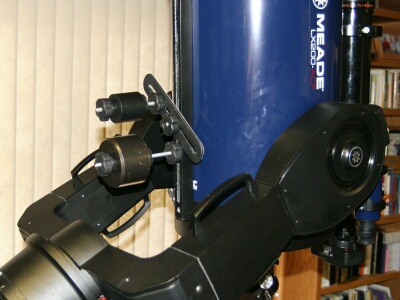 |
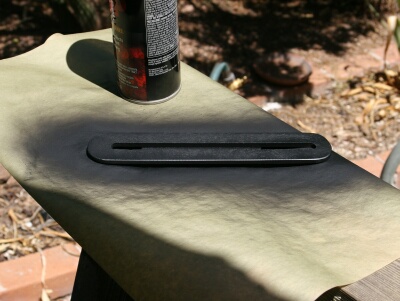
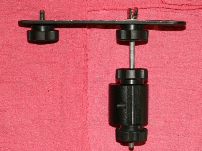
Typical setup showing the bar that gives this project its name. Large weight is on-center for the ED80 up top. |
|
Running a dew shield and maybe a heater to boot? Need some weight WAY back? Need it down for something piggyback - or up without the piggyback load? |
|
 |
 |
|
Want to do this easily, using whatever weights you have close at hand? Read on. I have used this system for more than 10 years on my (various) LX200s. I wouldn't trade it for anything I can buy, and you can build it with common hand tools for less than $50. No kidding! Well, if you do your hardware shopping at Nieman Marcus, it might set you back $75. Here's what you will need 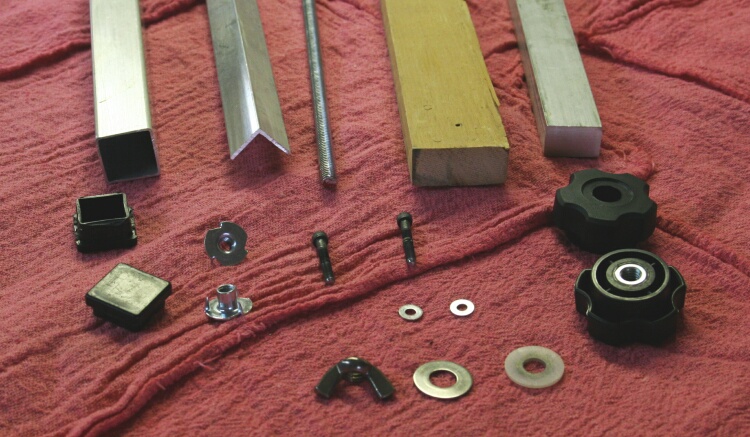
The Build
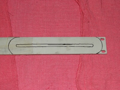
We'll start by making the slotted "sidewinder" bar. 3/16" x 2" aluminum, 8-9" long: |
|
 |
 |
 |
 |
|
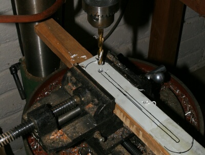
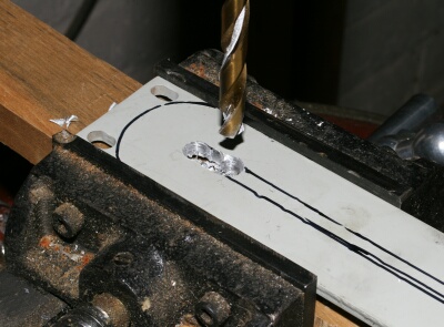
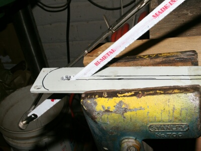
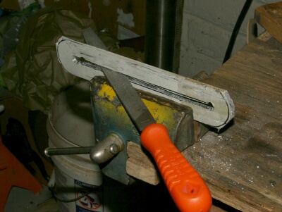
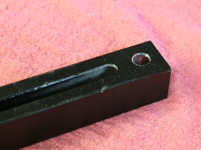
Layout the rough outline of the Sidewinder Bar on the flat stock. Don't worry too much about precision, just mark the slot a little narrower than your final cut. The 5/16" all thread needs to fit inside the slot loosely for easy adjustment. Drill end holes for the slot - I used 11/32" as my drill size, and at one end drill a couple more holes almost on top of each other so you can get a hacksaw blade through. Thread a hacksaw blade in, put the saw together, and cut your rough slot. |
|
 |
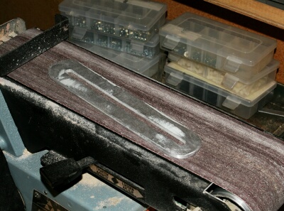 |
| Rough-saw the ends to reduce the filing you'll need to do, and finish the bar with your choice of rasps and files. Then sand the bar to a finish that suits your taste. |
|
 |
 |
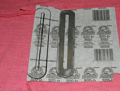
| Trace your finished bar on the back side of a piece of 320 grit sandpaper, cut out the trace, and mask the inside and outside of the bar to keep the spray glue off everything but one side. Glue the sandpaper on with whatever adhesive you prefer. I like 3M #77. The sandpaper is to give the flat bar some "tooth", and keep it from pivoting when you have it clamped in place. You don't HAVE to use it, but it sure reduces the clamping force required. (Yes, the sandpaper DOES scuff the mounting tube some, but what the heck, it's dark and nobody will see...) |
|
 |
 |
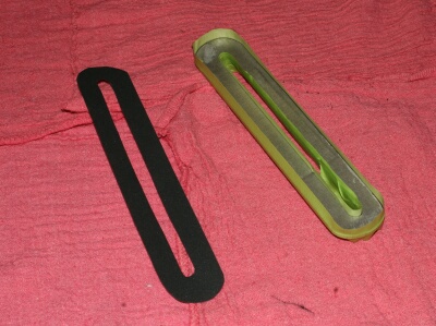
| Once you have the sandpaper glued on one side, turn the bar over and give everything but the sandpaper side a coat of your favorite paint. I like Ace Hardware "Barbecue Black", but paint is optional - suit your own taste. On to the main tube Using the same techniques, cut a slot in one side of the aluminum square tube. The tube should be cut to length to fit your scope tube, and the slot should extend to about 1" from each end of the tube. Again, precision isn't necessary, the 5/16" all-thread just needs to be able to slide (loose and sloppy) back and forth in the slot. IT IS IMPORTANT THAT THE SLOT BE STRAIGHT. You'll discover why if you get yours crooked. Since you can't get a standard hacksaw through the tube, use one of the many "mini hacksaw"-type hacksaw blade holders that leave a stub end of the blade out in the open and provide a decent handle. Don't despair the job - It won't take more than about 15-30 minutes tops to cut the rough slot with the blade holder. The aluminum is thin and soft. DO use a new, sharp hacksaw blade. |
|
Mounting the tube: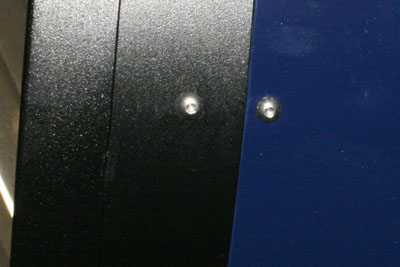 |
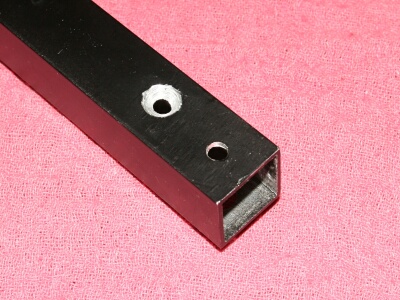 |
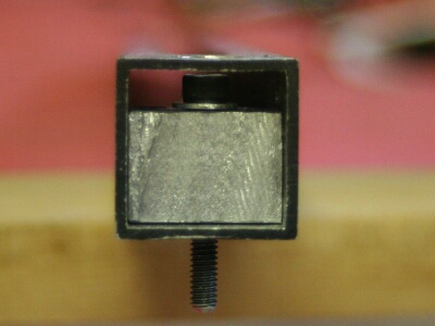
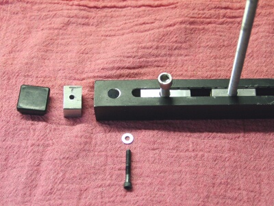
| On the bottom centerline of your OTA are FOUR screws. Two in the end castings, and two in the tube. DO NOT REMOVE THE TWO FROM THE TUBE. Find the PROPER SIZE hex wrench, and remove the two (outermost) screws from the end castings. There is probably Locktite on these screws, so be careful to get a good, solid fit with your hex wrench, and hold it firmly in place while you break the Locktite loose with a quick, firm snap-action. Hold on to these screws, we will need them later to measure the length of the new mounting screws. VERY CAREFULLY measure the center-to-center distance of the two empty holes, and the distance from these holes to the centers of the screws you left in the tube. Layout the locations for the two outermost screws on the TUBE SIDE (NOT THE SLOT SIDE) of your new square tube, centering everything up as best you can fore-to-aft. Using a center punch through masking tape is a good way to do this. Also center punch the locations of the two screws you left behind. When we mount everything, the two screws you left behind may (slightly) interfere with our square tube, so use an over-sized drill and cut some clearance relief for them. Drill mounting holes straight through both sides of the square tube with a drill bit just slightly larger than the #8 mounting screws you bought (or the #8 screws you just took out). Check for fit, but DO NOT RUN YOUR NEW MOUNTING SCREWS ALL THE WAY IN. THEY MUST BE CUT TO THE PROPER LENGTH BEFORE YOU DO. |
|
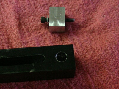
| When you're satisfied with the way the square tube fits, build the mounting blocks for it |
|
 |
 |
| I used aluminum because I had some, but hardwood will work just as well. If you do use wood, add a scrap piece of aluminum epoxied across the top so the screw won't bite directly into the wood. These blocks need to stay tight. Fit the blocks as shown, and drill out the mounting hole ON THE SLOT SIDE OF THE TUBE to some comfortable diameter (3/8" or so) to allow easy access to the screw and washer. Aim for a snug fit on the sides and bottom.
The reason we recess the mounting screw down inside the square tube is so there won't be a screw head sticking up in the way later when we want to pivot the Sidewinder Bar straight back (or nearly so). The mounting blocks need to be short enough to allow the plastic trim caps to push into place (I trimmed the insert part of my caps down to about a 1/4" height - as they come from the hardware store they tend to be much longer than needed for this application). |
|
| This is a good time to trim those mounting screws to the right length. |
|
 |
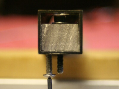 |
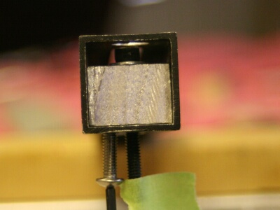
| Put the square tube and mounting blocks together with your new screws in place, and use one of the screws you took out to measure for the proper length.
A good way to get this right is to use a piece of masking tape. Note that we measure to the end of the threaded part of the screw - not to the top of the head. Cut the screws to length using any method that suits you, clean up the threads on the newly cut ends, and check for final length. |
|
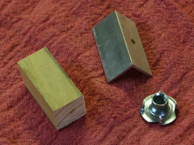
| Now for the sliding clamp blocks |
|
 |
 |
 |
 |
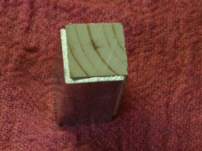
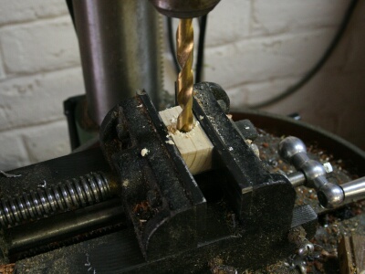
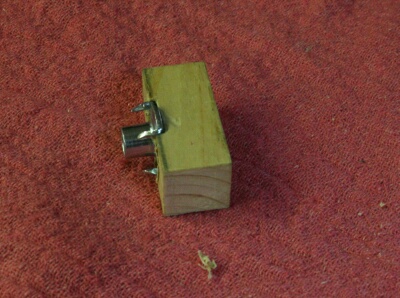
| Cut two wood hardwood blocks 3/4" square by 1 1/2" long. Also cut two pieces of 7/8" x 7/8" x 1/16" aluminum angle to 1 1/2" lengths. Find those 5/16" Blind nuts you bought.
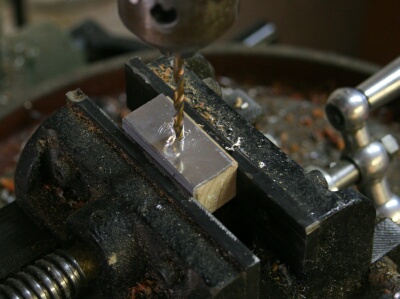
Fit the wood and the angle as shown. Clamp or place in a vice, and drill from the aluminum side all the way through with a small (1/8") pilot drill IN THE CENTER OF THE "SANDWICH" THIS WILL NOT BE IN THE CENTER OF THE ALUMINUM. Drill all the way through with a bit just slightly larger than 5/16" (11/32 is about right) so the all-thread will slip easily through without too much slop. |
|
 |
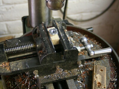 |
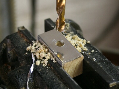
| Turn the slider over and drill about half-way through with a bit that is just snug to the outside diameter of the blind nut tube. For me, this was a 3/8" drill.
Test fit the blind nut in the hole. |
|
 |
 |
 |
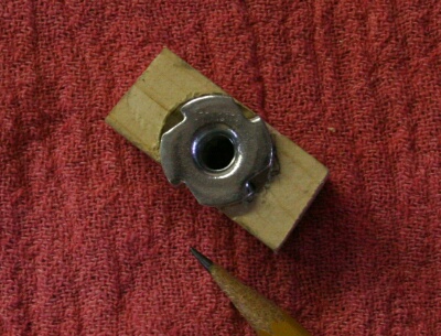 |
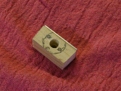
| Mark the outline of the blind nut, and the location of the prongs. Drill small (1/16") leader holes at the prong locations to prevent splitting.
Carve out a recess for the blind nut head. Use any method that suits you - I used a Dremel. You'll know you're deep enough when the blind nut is just flush when you put in place backwards. Part of the blind nut will need to be trimmed. Grind or file off the part that hangs over the edge. |
|
 |
 |
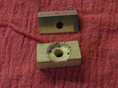
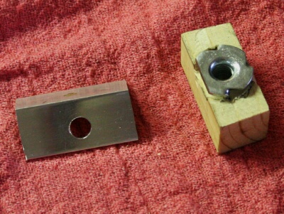
| Final check your fit, and rough up the contact areas of the angle and the blind nut with coarse sandpaper.
Epoxy all three parts together, being careful not to get epoxy too deep in the blind nut hole or in the threaded section of the nut. Clamp everything in a vise or other clamps, driving the blind nut in solid and squeezing the whole sandwich tight. Do it all over again while the epoxy cures. You will need two sliders. When the epoxy has cured on the first slider, check it for fit. It should slide (loose and free) the full length of the square tube. Be sure to check it with a 5/16" bolt or all-thread in place, to be sure you got your slot right. Refit (file) as required. |
|
| Bringing it all together |
|
 |
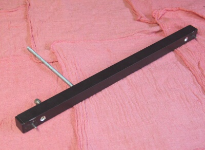 |
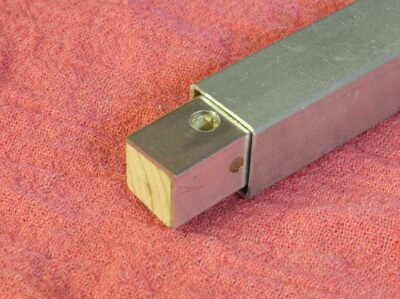
| Slide the sliders into the square tube and hold them there by threading in 5/16" bolts or sections of all-thread. Tighten just enough to keep them from falling out while you get things done. BE SURE THAT THE ALUMINUM ANGLE - NOT THE BLIND NUTS - IS SHOWING THROUGH THE SLOT. Fit the mounting blocks, washers and screws, and end caps to the tube, and head for the scope. Before you put the tube up to the scope, make one final inspection of the threads on the mounting screws. Be sure you have cleaned up the burrs. Thread the screws into something else to be sure they go in easily. You will be putting a steel screw into an aluminum casting. Any burrs can damage the threads on your scope casting. Don't risk it! Do a final test fit, fix anything that isn't just right, and then put a dab of BLUE Locktite on the mounting screws and tighten them firmly, but DO NOT OVER-TIGHTEN. Use care. And finally, we get to the weights... |
|
 |
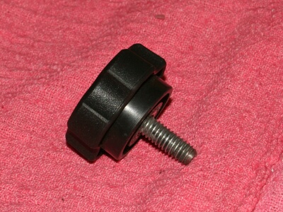 |
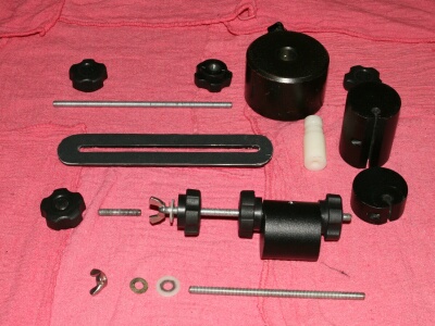
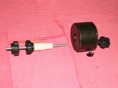
| Start cutting pieces of all-thread to make up your weight rods. Cut one short piece to be the clamp stud that holds the Sidewinder Bar in place as shown above, and secure the stud in the knob with RED Locktite. The length of this stud is critical. When the stud is clamping your bar tight, with any washers you plan to use in place, the stud should be about one turn from fully seated against the back wall of the tube. You will have to experiment with the exact placement of the stud before using the red Locktite. Cut other pieces of all-thread to suit the weights you have, and swing clearance of your mount. Take your time and check different placements. If you don't get it right the first time, at least all-thread is cheap. |
|
 |
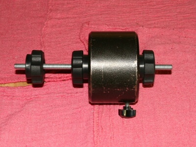 |
| When running a heavy pigyback load, it's nice to be able to use larger weights. This one is a 7 lb. from my LXD75, and it has a 3/4" bore. Make up some kind of bushing (this one was made from nylon) to keep the weight centered on the rod. It doesn't have to be a critical fit, and the weight clamp doesn't have to engage anything - our clamping knobs do the securing. Bits of PVC pipe, plactic tubing, adding machine paper cores, Junque of most any sort will do for a bushing. Duct Tape around a piece of 3/8" ID copper pipe has been used... |
|
 |
You may have noticed that most of my weights (all the small ones) are NOT centered on the rod. They are standard Meade weights that came with my original LX200 many years ago, and they are built that way. This system was originally designed to make use of these weights in a 3-D environment. That's where the 5/16" rod size came from. The off-center feature of the Meade weights is actually an advantage. In many cases, where a small weight shift is needed, you can loosen a knob, rotate a weight a bit, and get the shift you need. |
|
IMPORTANT NOTE: When mounting the straight rod, thread the rod into the slider until it just contacts the back side of the square tube, and then back it out about one turn. Hold the rod steady, and turn the clamping knob to take the tension and hold the rod in place. The clamp must occur between the face of the sliding block, the tube, and the clamping knob. If the rod is holding the block by pressing against the back of the tube, there will be only a tiny contact area for clamping, and the block could slip out of place at a time when it would not be appreciated.
Comments, questions and inquiries are always welcome! Contact Dave Graham |
|
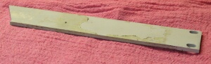 (Forgot to put this in the photo above) - A piece of aluminum flat bar.