| How the Power Box Was Built |
|
| Here's the build: The box is a Radio Shack project box 8"x6"x3" that has a metal bottom that makes a nice chassis mount/filter holder - about $7. It fits nicely into the notch at the North end of my Super Wedge.
|
|
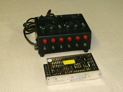 Finished box and switching supply module | 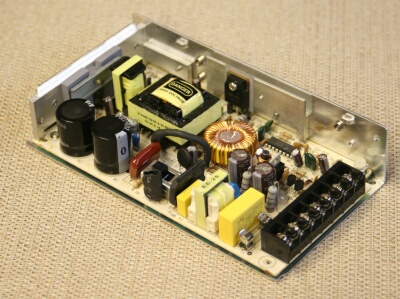 Pull the cover - There's work to be done! |
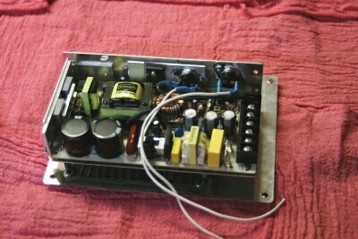
| For our purposes, we need to make some changes to the switching supply unit: |
|
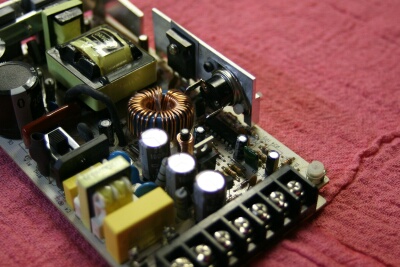 Upper right: Main Thermostat | 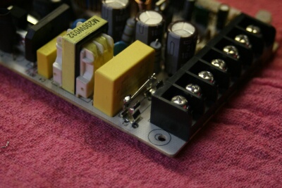 Lower: Shorted on-board fuse holder |
| A 40 deg.C (104 deg.F) thermostat was installed on the primary heat sink right next to the output transistor. It's connected to Fan #1. Since we don't ever expect to be back in here, we remove the on-board fuse and solder a wire across the fuse holder. We'll fuse the AC right at the power cord instead. Not Shown: There's a switch on the main board to select 110v or 220V AC input. Mechanical things fail. Switch contacts eventually DO corrode. Eliminate the issue: Solder jumpers on the back side of the circuit board to make this unit permanently 110V, and forget about the switch. One less thing to go wrong. |
|
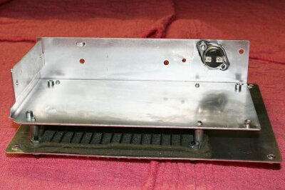 Chassis and secondary T-stat | 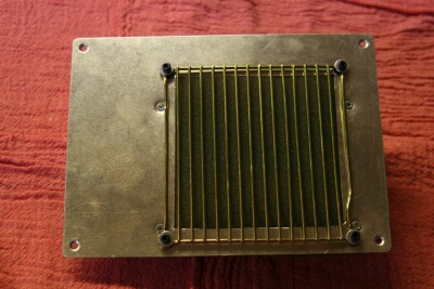 LARGE opening for filtered air |
| Another 40 deg. C. Thermostat is installed on the chassis, insulated with .050" nylon. It will run fan #2. It will take the heat longer to set this one off. If the first fan can't hold the heat load (or fails) this is our backup. Fans are mechanical. They fail. Belt and suspenders. In testing, with a 8A load (the most that I will ever likely pull) and 85 deg. F ambient air, fan #1 came on after 6 minutes. Fan #2 came on after 11 minutes, cycled off at 19 minutes, and back on at 23 min. With a 2.5A load, it ran for two hours and neither fan came on. At 4 Amps load, Fan #1 cycled on and off. On a cool evening, you might run 4-6Amps all night and never need a fan. The fans are whisper-quiet (selected to be that way). Note: The switching unit is rated by the manufacturer at 12.5Amps, continuous, on convective cooling only. It's also rated to run at 80 deg. C. I don't plan to ever ask it for more than 10A, and normally I won't need more than 7.5A peak and 5A continuous. This de-rating of all the components should mean long life, cool operating temperatures, a quiet night, and most of all, the highest reliability I can ensure. The opening for air (convective or forced) is as large as the situation will allow. Two layers of 3/16" filter foam hopefully keep most of the crud out. |
|
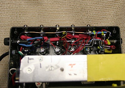
 Chassis/Box bottom assy |  Camera port, Banana Plugs |
| On the left is the chassis bolted together and wired up for the fans. 1/2" standoffs allow for good airflow around the chassis. On the right, note the odd power socket. It's different because it's for the camera. Also note the Banana sockets. They are connected directly to the bus rails, and allow for a 12V input feed, a meter connection, an (unfused) output for something strange, or whatever. The 12V output connectors are RCA jacks. All are not created equal. Good ones can handle more than 10A without getting warm. On to the Camera Power Supply |
|
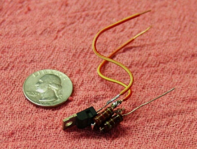 Naked Camera Power Supply | 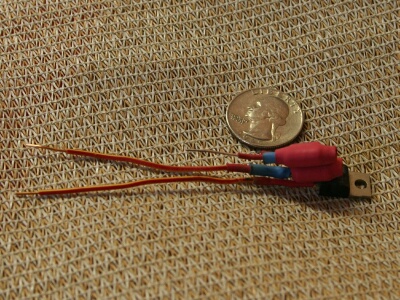 Somewhat clothed |
| Power for the Canon SLR is provided with a tried-and-true LM317 voltage regulator chip. It needs only two external components (in this case 4, as I matched values by combining resistors). | |
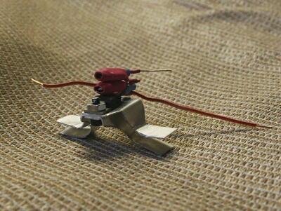 Heat Sink - A.K.A. Millennium Falcon |  Camera power supply - a bird in a tight nest |
| A heat sink for the LM317 was fashioned from 0.020 Aluminum, and the whole assembly gently fitted into the only space available. Note insulation installed everywhere in the vicinity of the camera power supply. The heat sink has camera output voltage on it. Camera voltage note: Canon batteries are labeled 7.4V. The battery charger is labeled 8.4V. The 110V Adapter is labeled 7.4V, but actually puts out 7.8V with a 500MA load connected. A freshly charged camera battery measures 8.39V, and drains to 8.2V after the camera has been running for 15 min. I settled on 8.3V at the box, which gives 8.2V at the end of 18' of 20 ga. wire (the longest run I would ever use), and the camera likes it. The camera shows a full battery on the indicator, and only drops down one bar less than full for a split second after you fire the flash. (I know, we don't plan to EVER fire the flash, but the moment after the flash is fired represents the maximum current the camera can draw from its power supply - almost 1 Amp. - so this is our worst case test point. Test passed.) |
|
 Down deep, the red sleeves insulate the filter chokes | 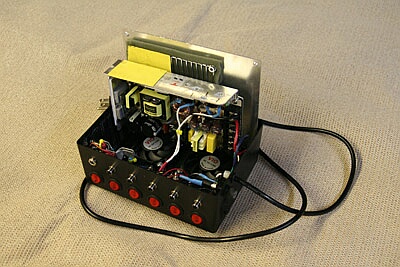 Ready for bench testing - yellow insulation sheets for camera supply regulator |
 Up and running - first real test - All Systems GO! | Not pictured because I forgot to take a picture before I had everything closed up: The "Crowbar" - a 35-Amp SCR and the 12.6V Zeiner diode circuit that fires it. As mentioned above, this is the "last-best line of defense" against over-voltage harming our electronics. It's as close to foolproof and bulletproof as anything I know how to build. I'm not worried about this unit hurting my gear. |