Power Supply Test and Evaluation
|
|
The Quest for Clean Power - Reaching for the Flat Line
|
|
| Power supplies are among the least-understood, and most-often-maligned pieces of gear in our inventory. Before delving into the details of the Power Box tests, here is some general information about power supplies that may help put our test results in a clearer context. |
|
|
Volts, Amps, Filters and Waveforms
Judging the performance of a power supply isn't as simple as taking a voltage reading. I can't count the number of posts to newsgroups and forums that said "I think my power supply has fried my scope. I put a meter on my 12V supply and it reads 21V. I'm looking at big $$$..." or "I put a meter on my power supply and it is dead. I'm going to have to get a new one..." I also can't imagine how much money has been wasted chasing after "bad" power supplies that were working perfectly. |
|
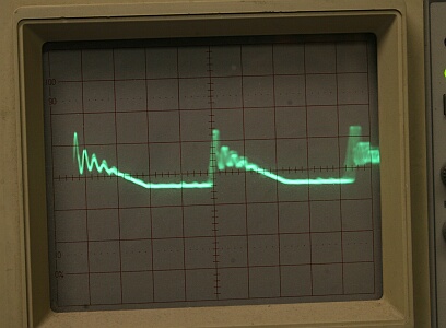  Above: Output of a power adapter for a name-brand DSLR and the "flat line" of a battery. NOTE: The power adapter output shown above IS NOT BAD. The ringing shown is about 0.18V peak-to-peak, or 2% of the 8.3V the adapter is putting out. This is within the expected tolerance for this type of unit. FACT: Most power supplies will put out their designed voltage only when connected to their designed load, and many switching-type supplies will not work at all unless they are connected to some kind of load. FACT: The electronics in more scopes, cameras, etc. have failed when they were "Zapped" by a static discharge or a "spike" on the commercial power feed than all other causes combined. Run your 120V stuff through a computer-style UPS, and use static control to keep this from happening to you. Back to figuring out power supplies: If you connect a voltmeter to a typical consumer-grade unit (without plugging it into whatever it was designed to power), you will probably read a voltage that is considerably different from what it says on the label. If it is a transformer-type (most older designs are), you could easily read a voltage near TWICE that on the label. Most switching power supplies do put out close to their rated voltage if they are working at all. The only way to be sure is to hook the supply up to a known load, and then measure the Volts, Amps, and if you still suspect that something's wrong, have a look at the waveform on a 'scope. Transformer-type and switching-type power supplies both can be perfectly acceptable. What's the difference? Transformer power supplies use windings of wire around an iron frame to form two electromagnets that "transform" AC power from one voltage to another. The ratio of the voltages is in direct proportion to the ratio of the number of winds in each coil. A 120/12V transformer might have 100 turns of wire in the primary coil, and 10 turns in the secondary coil. Switching power suplies use an electronic switch to turn the incoming power on and off like a wall switch. They just do it VERY FAST, (70,000 times a second is not unusual) and they only turn the power ON for a very short time, and then leave it OFF for a much longer time. Built-in electronic regulators and filters take these short pulses of 120V power and filter it down to an almost-smooth DC Voltage. Switching supplies are far lighter (and smaller) than equivalent transformer types, are almost completely silent (no transformer hum), can be easily "tweaked" to provide the exact voltage we need, and come off-the shelf with the ability to compensate for wide fluctuations in input power voltage and quality. Switching Supplies are VERY efficient (run cooler). They only switch on as much power as is needed at the moment (and don't have to keep that big transformer energized). They can also react almost instantly to changes in output load. Good ones are extremely reliable. Seeing electricity An oscilloscope is to electricity what a microscope is to biology. An oscilloscope allows us to see very small things that might make our electronic equipment "sick". A waveform is the line traced on the face of the oscilloscope, with changes in voltage resulting in up-and-down swings of the line. The line goes across the oscilloscope display from left to right in whatever amount of time we select, depending how fast the things we are looking at happen. Below are examples of commercial power waveforms on a 'scope: 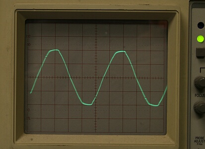 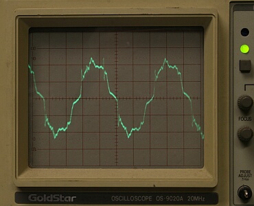 On the left, note that the trace of commercial power is not a perfectly smooth sine wave. Commercial power isn't perfect because all the lines, transformers, and things connected to the power grid (including everything in your house) all have an effect - "feeding back" distortions that appear everywhere on the grid. On the right, We've turned on the air conditioning, the electric clothes dryer, some dimmable lights, etc. Both of these traces are normal. Different equipment has different "immunity" to the small (or not so small) variations in the power that come out of our outlets and our equipment power supplies. Most electronics have a fairly high tolerance for these variations, allowing this output from a computer-grade UPS (uninterruptable power supply) to work just fine: | |
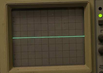
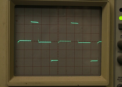 | At left: This typical UPS puts out a square waveform. Some (more expensive) units put out various modified or even pure sine waves. You wouldn't want to run a motor on this square wave, but computers, telescopes and most everything electronic can run on this just fine because they use a separate AC to DC power supply (built-in, Wall Wart, etc.) that can run on this kind of waveform. |
|
The only TRUE clean power comes from a battery. Although we often "dirty it up" when we connect something to it, a battery by itself puts out a pure, "flat" voltage. All AC-to-DC power supplies, even laboratory-grade (and very expensive) units, have some distortion in their outputs. The 'scope allows to see this distortion and measure it, so we can decide if the output of the power supply is "good enough", and what's good enough for the goose may not be good enough for the gander. Every piece of equipment has its own tolerance for noise and distortion on its input power, and every piece of equipment "feeds back" some level of noise toward the supply that feeds it. 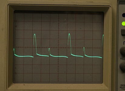 Left: Scope trace for a battery. Right: What happens when we connect that battery to a standard computer cooling fan through 6ft. of wire. The fan motor "kicks back" about 1.3V of "noise". So much for our flat line... Takeaway: Running a cooling fan for a TEC module on the same circuit as the camera it's cooling can lead to funny things happening in the camera. Getting rid of the noise - Filters Filters are components we insert into our power circuits in an attempt to "flatten out" the distortions and "noise" as we try to make our "created" power look more like a battery. 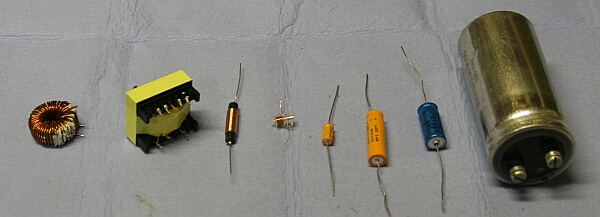 Common filter components - inductors on the left, capacitors on the right. Think of driving on a bad road, and wishing it were smooth. Inductors knock the sharp points off the rocks, and capacitors help fill in the chuckholes before we hit them. For this project, I opted for inductors only. Capacitors rank among the least-reliable components in electronics, and the results were more than acceptable without using them in the final output stages of the Power Box. Important Concept: Filters don't filter unless current is flowing: 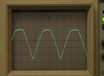 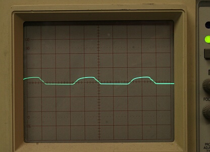 Left: Output of a 12V Wall Wart not plugged into device. Right: Same Wall Wart when powering its device (1.1V ripple). The photos above show why it isn't possible to accurately measure the output of a power supply that isn't connected to its designed load. A DC voltmeter measures the trace on the left as 18.7V, and the one on the right as 12.3V. The unfiltered ripples drive the voltmeter crazy. Transformer-types (Above) "Ripple" - Switching-types (Below) "Ring" 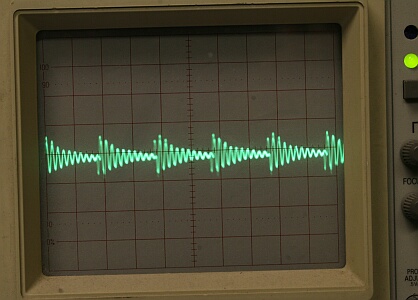 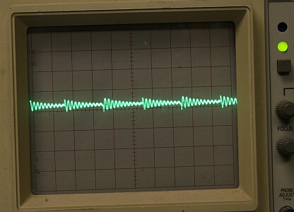 Left: Power Box main board output - no load - 70mV noise Right: Power box main board trace at 10A load - 40mV noise Note: Both the time scales and the amplitude scales are different for the Wall Wart and Switching photos. The Wart's ripple is almost 20 times greater in amplitude than the switch's ring, and the ring happens 500 times for each ripple. Loaded switch ring = 0.04V (0.3%)- Loaded Wart ripple = 1.1V (8.9%). Compare the waveforms of the Power Box (switching-type) and the Wall Wart. The Wart is a transformer type, and it "ripples" 120 times each second (in sync with the AC line feeding it). The Power Box main board is a switching power supply and it "rings" about 70,000 times per second (each tapered "cone" is one ring). In both cases, note that the load makes a big difference in the apparent "quality" of the power. The Wart's unloaded ripple is 18V (100% ripple). Loaded, this drops to about 1.1V, (about 9%). For the Power Box, the ring of the unloaded output of the main board is 70mV (0.5%). Loaded to max, the Power Box's main board ring drops to 40mV (0.35%). Takeaway: Buying an over-sized power supply won't get you better quality power. In fact, it may be worse, since the connected load may not be enough to make the filter circuit work efficiently. We're getting closer to acting like battery power, but there's one step remaining. Working towards the flat line: Individual filters for each power circuit. On the bench, I measured the actual current demand for each device to be powered by the box. There are some trade-offs here: The scope uses more power when slewing (especially if slewing fast in both axes) than while just tracking along. It uses less power if well-balanced, etc. The DSLR uses short peaks of power when cycling the mirror, dumping the imaging chip to USB, and so on. Experimentation was the final solution after getting into the ball park through calculations. In each case, the aim is to run the inductor in each circuit just short of its saturation point during the highest expected current demand. Some of the choices were easy - forget about those fast slews (I don't like them anyway). Final results: First, the big picture What about that flat line? Scope traces below are at 1.0V/square. 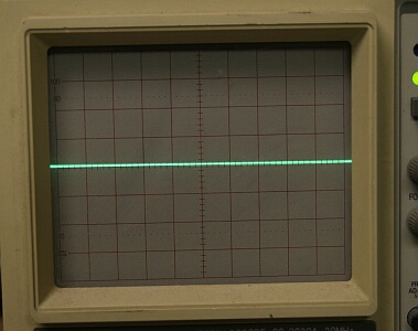 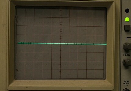 You can just see some fuzziness in the line on the left. It's the Power Box with everything connected and running. Battery power is the line on the right. Close enough for me. Now, under the microscope - 50mV/square: 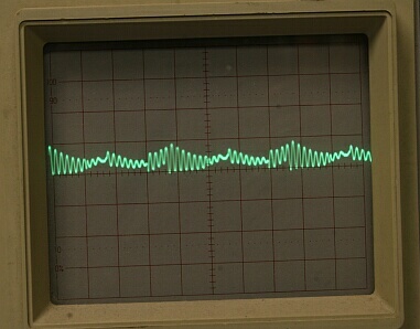 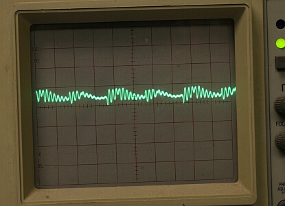 Left: Camera port - Camera Idle - 45mV Right: Camera port - Camera downloading - 40mV 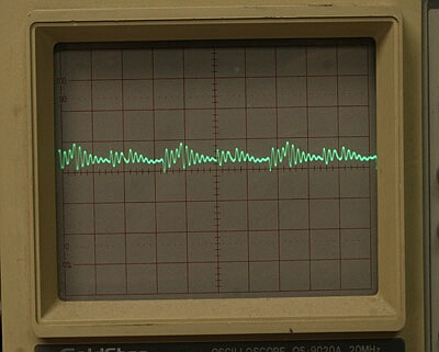 Left: LX200 - RA Tracking - 60mV Right: LX200 - Slew 3deg./sec. (both axes) - 45mV Bottom Line: Cleaner power (by far) than any manufacturer-supplied power supply I tested, and plenty of it for all my needs. Total distortion: less than 0.5% on all circuits at all routine loads. Worst-Case maximum distortion measured (only one circuit running on lightest load): 70mV (0.57%). SAFE power - under voltage & over voltage compensation, over current (short circuit) protection for all supply circuits and the main board itself. I'll keep it, and I expect it to serve my needs for a long time. |
|